In the air conditioning test room, when measuring the cooling capacity (or heating capacity) of the water side of the water machine, the inlet and outlet water temperatures and water flow of the prototype are usually measured, and then the cooling capacity (or heating capacity) is calculated. The water flow here is basically measured with an electromagnetic flowmeter.
Below we introduce the relevant knowledge of electromagnetic flowmeters.
1. Scope of application of electromagnetic flowmeter
Electromagnetic flowmeter is suitable for measuring the volume flow of conductive liquids in closed pipes, such as clean water, sewage, various acid, alkali and salt solutions, etc.
The fluid for measuring flow with electromagnetic flowmeter must be conductive, so non-conductive gas, steam, oil, copper and other materials cannot be measured with electromagnetic flowmeter.
2. Working principle of electromagnetic flowmeter
The measurement principle of the electromagnetic flowmeter is based on Faraday's law of electromagnetic induction: when a conductive liquid cuts magnetic lines of force in a magnetic field, an induced potential is generated in the conductor, and the induced electric heat E is:KBVD
Where:
k--------Instrument constant
B--------Magnetic induction intensity
V--------Average flow velocity in the measured pipe section
D--------Inner diameter of the measured pipe section
When measuring flow, the conductive liquid flows through a magnetic field perpendicular to the flow direction at a speed V. The flow of the conductive liquid induces a voltage proportional to the average flow velocity. The induced voltage signal is detected by two or more electrodes in direct contact with the liquid and sent to the converter through a cable for intelligent processing, LCD display or conversion into a standard signal 4-20mA output.
3. How to choose electromagnetic flowmeter correctly
●Collect data:
(1) Type of fluid to be measured; (2) Maximum flow rate, minimum flow rate; (3) Maximum working pressure; (4) Maximum temperature, minimum temperature.
● The fluid to be measured must have a certain conductivity, with a conductivity of ≥5μS/cm.
●The maximum flow rate and minimum flow rate must meet the values in the following table
● The actual working pressure must be less than the rated working pressure of the flowmeter.Inner diameter(mm) DN10 DN15 DN20 DN25 DN32 DN40 Qmin(m³/h) 0.0848 0.1908 0.3391 0.5299 0.8681 1.3565 Qmax(m³/h) 3.39 7.63 13.56 21.2 34.73 54.26 Inner diameter(mm) DN50 DN65 DN80 DN100 DN125 DN150 Qmin(m³/h) 2.1195 3.5820 5.4259 8.478 13.246 19.075 Qmax(m³/h) 84.78 143.28 217.04 339.12 529.98 763.02 Inner diameter(mm) DN200 DN250 DN300 DN350 DN400 DN450 Qmin(m³/h) 33.912 52.9875 76.302 103.85 135.648 171.68 Qmax(m³/h) 1355.5 2119.50 3052.1 4154.2 5425.9 6847.5
● The maximum working temperature and the minimum working temperature must meet the temperature requirements specified by the flowmeter.
● Try to avoid negative pressure at the flowmeter. If the sensor lining is not selected properly, negative pressure will cause the lining to deform and cause leakage.
●You can select the corresponding electromagnetic flowmeter according to the flow rate in the above table. If the inner diameter of the selected electromagnetic flowmeter is smaller than the inner diameter of the process pipeline, the pipe should be reduced. Generally, in order to prevent bubbles from being retained at the flowmeter, the inner diameter of the selected flowmeter cannot be larger than the inner diameter of the pipeline.
● If the pipeline is reduced, it should be considered whether the pressure loss caused by the reduction will affect the process flow.
Electromagnetic flowmeter inner diameter, flow velocity and flow rate relationship curve:

When measuring clean water, the economic flow rate is 1.5-3/m/s, and in actual application it rarely exceeds 7m/s. Since the laboratory's prototype test water system is equipped with a water pump, if the selected flow meter has a flow rate that is too large, it means that the pipe diameter is too small and the local resistance is large, which may cause insufficient pump head.
For split electromagnetic flowmeters, the longer the cable, the greater the possibility of signal interference. In actual application, the shorter the split distance, the better. The laboratory has very high requirements for measurement accuracy, so it is best to use an integrated flowmeter.
4. How to correctly select the installation point of the electromagnetic flowmeter
●Select a straight pipe section filled with liquid, such as a vertical section of the pipeline (preferably flowing from bottom to top) or a horizontal pipe filled with liquid (preferably the lowest point in the entire pipeline). During installation and measurement, the pipe must not be partially filled.
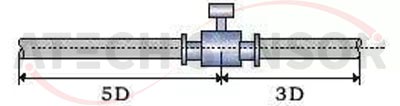
● The electromagnetic flowmeter measurement position should be selected at a straight pipe section with a length greater than 5D upstream and 3D downstream.
●The measurement point should be selected as far away from pumps, valves and other equipment as possible to avoid interference with the measurement.
●The measurement point should be selected as far away from high-power radio stations, strong magnetic field interference sources, etc.
5.Electromagnetic flowmeter installation instructions
(1)The axis of the measuring electrode must be approximately horizontal:

(2)The measuring pipe must be completely filled with liquid.
(3) There must be at least a 5×D (D is the inner diameter of the flowmeter) straight pipe section in front of the flowmeter, and at least a 3×D (D is the inner diameter of the flowmeter) straight pipe section in the back.
(4) The flow direction of the fluid should be consistent with the direction of the arrow on the flowmeter.
(5) There should be ample space near the flowmeter for installation and maintenance.
(6) If the measuring pipeline vibrates, there should be fixed supports on both sides of the electromagnetic flowmeter.
6. Electromagnetic flowmeter installation requirements
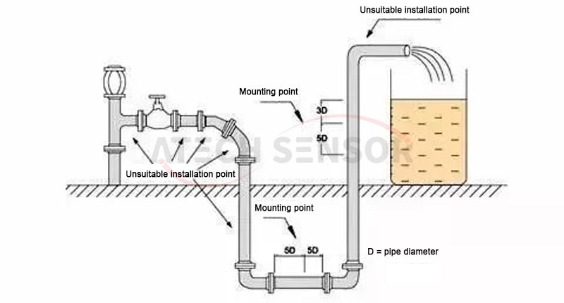
(1) The electromagnetic flowmeter should be installed at the lower part of the horizontal pipeline and vertically upward, and avoid being installed at the highest point of the pipeline and vertically downward:
(2) The electromagnetic flowmeter should be installed at the rising part of the pipeline:

(3) When installing the electromagnetic flowmeter in an open discharge pipe, it should be installed at the lower part of the pipe;

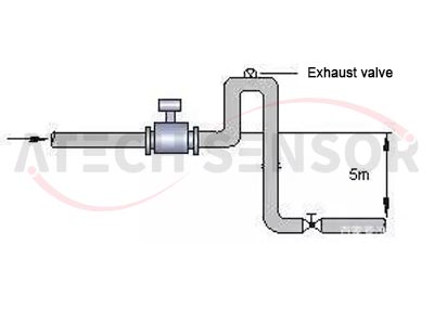
(4) If the pipeline drop exceeds 5m, install an exhaust valve downstream of the electromagnetic flowmeter;
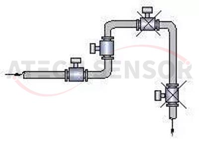
(5) If control valves and cut-off valves are installed on the pipeline, they should be installed downstream of the flow meter, not upstream of the electromagnetic flow meter;

(6)The electromagnetic flowmeter must not be installed at the inlet of the pump, but should be installed at the outlet of the pump;

7. Typical fault diagnosis and treatment
(1)No flow output. Check whether there is a fault in the power supply part and test whether the power supply voltage is normal; test the fuse; check whether the sensor arrow is consistent with the fluid flow direction. If not, change the sensor installation direction; check whether the sensor is full of fluid. If not, replace the pipe or install it vertically.
(2) The signal is getting smaller or suddenly drops. Test whether the insulation between the two electrodes is damaged or short-circuited. The resistance value between the two electrodes is normally between (70 and 100)Ω; dirt may be deposited on the inner wall of the measuring tube. The electrodes should be cleaned and wiped, and the lining should not be scratched. Whether the measuring tube lining is damaged, if damaged, it should be replaced.
(3)Zero point is unstable. Check whether the medium is full of the measuring tube and whether there are bubbles in the medium. If there are bubbles, install an air eliminator upstream. If it is installed horizontally, it can be changed to vertical installation; check whether the instrument grounding is intact. If not, three-level grounding should be performed (grounding resistance ≤ 100Ω).
(4)The flow indication value does not match the actual value. Check whether the fluid in the sensor fills the tube and whether there are bubbles. If there are bubbles, install an air eliminator upstream. Check whether the grounding conditions are good. Check whether there is a valve upstream of the flow meter. If so, move it downstream or fully open it. Check whether the converter range setting is correct. If not, reset the correct range.