Data acquisition (DAQ) refers to the automatic collection of non-electrical or electrical signals from analog and digital units such as sensors and other devices under test, and sending them to the host computer for analysis and processing. The data acquisition system is a flexible, user-defined measurement system that combines measurement software and hardware products based on computers or other dedicated test platforms.

1.Introduction
Data acquisition, also known as data acquisition, is an interface that uses a device to collect data from outside the system and input it into the system. Data acquisition technology is widely used in various fields. For example, cameras and microphones are data acquisition tools.
The collected data are various physical quantities that have been converted into electrical signals, such as temperature, water level, wind speed, pressure, etc., which can be analog or digital. Collection is generally a sampling method, that is, the same point data is repeatedly collected at a certain interval (called sampling period). Most of the collected data are instantaneous values, or they can be a characteristic value within a certain period of time. Accurate data measurement is the basis of data acquisition. Data measurement methods include contact and non-contact, and there are many kinds of detection elements. Regardless of the method and element, it is based on the premise of not affecting the state of the object being measured and the measurement environment to ensure the correctness of the data. Data acquisition has a wide meaning, including the collection of continuous physical quantities in the form of surfaces. In computer-aided mapping, mapping, and design, the process of digitizing graphics or images can also be called data acquisition. At this time, the data collected is geometric quantity (or physical quantity, such as grayscale) data.
With the rapid development of the Internet industry, data acquisition has been widely used in the Internet and distributed fields, and important changes have taken place in the field of data acquisition. First, intelligent data acquisition systems in distributed control applications have made great progress at home and abroad. Secondly, the number of bus-compatible data acquisition plug-ins continues to increase, and the number of data acquisition systems compatible with personal computers is also increasing. Various data acquisition machines have been launched at home and abroad, bringing data acquisition into a new era.
2. Production data
Smart manufacturing cannot be separated from the support of workshop production data. In the manufacturing process, CNC machine tools are not only production tools and equipment, but also nodes of the workshop information network. Through the automated collection, statistics, analysis and feedback of machine tool data, the results can be used to improve the manufacturing process, which will greatly improve the flexibility of the manufacturing process and the integration of the processing process, thereby improving the quality and efficiency of the product production process. Gallup MDC system helps enterprises solve this problem.
The MDC system is mainly used to collect the working and operating status data of CNC machine tools and other production equipment, realize the monitoring and control of the equipment, and analyze and process the collected data. It can also provide data support for other software such as MES and ERP. The MDC system is an integration of the machine tool data acquisition system and the machine tool data analysis and processing system. It is a workshop application management and decision support system with functions such as data acquisition, machine tool monitoring, data analysis and processing, and report output.
MDC realizes the automatic execution of the data collection part of the machine tool through intelligent integration with the CNC system, PLC system, and the electronic control part of the machine tool, without the need for manual input by the operator, thus ensuring the real-time and accuracy of the data. In terms of data mining, MDC provides enterprises with more professional analysis and processing, personalized data processing and rich graphic report display, and statistics and analysis of key data related to machine tools and production, such as machine start-up rate, spindle operation rate, spindle load rate, NC operation rate, failure rate, equipment overall utilization rate (OEE), equipment productivity, parts qualification rate, quality percentage, etc. Accurate data is transmitted and distributed to relevant process departments in a timely manner for processing, guiding, responding to and reporting the production dynamics of the workshop in real time, greatly improving the ability to solve problems and promoting the process of intelligent manufacturing in the enterprise workshop.
3.Purpose
Data acquisition is the process of automatically collecting information from analog and digital units under test, such as sensors and other devices under test. Data acquisition systems combine computer-based measurement hardware and software products to implement flexible, user-defined measurement systems.

The purpose of data acquisition is to measure physical phenomena such as voltage, current, temperature, pressure or sound. PC-based data acquisition uses a combination of modular hardware, application software and computers to perform measurements. Although data acquisition systems have different definitions based on different application requirements, the purpose of each system is the same: to collect, analyze and display information. Data acquisition systems integrate signals, sensors, actuators, signal conditioning, data acquisition equipment and application software.
4. Principle
Today, when computers are widely used, the importance of data collection is very significant. It is the bridge that connects computers to the external physical world. The difficulty of acquiring various types of signals varies greatly. During actual data collection, noise may also cause some troubles. When collecting data, there are some basic principles to pay attention to, and there are more practical problems to solve.
Assume that an analog signal x(t) is sampled once every Δt. The time interval Δt is called the sampling interval or sampling period. Its reciprocal 1/Δt is called the sampling frequency, and the unit is the number of samples per second. t=0, Δt, 2Δt, 3Δt... and so on, the value of x(t) is called the sampling value. All x(0), xΔt), x(2Δt) are sampling values. According to the sampling theorem, the minimum sampling frequency must be twice the signal frequency. Conversely, if the sampling frequency is given, the maximum frequency that can correctly display the signal without distortion is called the Nyquist frequency, which is half of the sampling frequency. If the signal contains components with frequencies higher than the Nyquist frequency, the signal will be distorted between DC and the Nyquist frequency.
The result of undersampling is that the frequency of the restored signal appears different from the original signal. This signal distortion is called aliasing. The resulting aliasing error is the absolute value of the difference between the frequency of the input signal and the nearest integer multiple of the sampling rate.
The result of sampling will be that the signal below the Nyquist frequency (fs/2=50Hz) can be sampled correctly. However, the signal components with a frequency higher than 50HZ will be distorted when sampled. Distortion frequencies F2, F3 and F4 of 30, 40 and 10Hz are generated respectively. The formula for calculating mixing deviation is:
Mixing deviation = ABS (integer multiple of sampling frequency - input frequency)
ABS stands for "absolute value",
To avoid this situation, before the signal is collected (A/D), it is usually filtered through a low-pass filter to remove the signal components above the Nyquist frequency. This filter is called an anti-aliasing filter.
How should the sampling frequency be set? Perhaps you may first consider using the maximum frequency supported by the acquisition card. However, using a very high sampling rate for a long time may result in insufficient memory or too slow hard disk data storage. In theory, it is enough to set the sampling frequency to twice the highest frequency component of the collected signal. In practice, 5 to 10 times is selected in engineering. Sometimes, in order to better restore the waveform, it is even higher.
Usually, appropriate signal processing is required after signal collection, such as FFT. Here there is another requirement for the number of samples. Generally, it is not possible to provide only one signal cycle of data samples. It is hoped that there are 5 to 10 cycles, or even more samples. And it is hoped that the total number of samples provided is the number of whole cycles. Here there is another difficulty. The frequency of the sampled signal is not known, or is not known exactly. Therefore, not only is the sampling rate not necessarily an integer multiple of the signal frequency, but it is also impossible to guarantee the provision of an integer number of samples. All are just discrete functions x of a time series (data acquisition cards, data acquisition modules, data acquisition instruments, etc. are all data acquisition tools.
5. On-site collection
For most manufacturing companies, automatic data collection of measuring instruments has always been a troublesome issue. Even if the instruments have RS232/485 and other interfaces, they still use the method of measuring, recording manually on paper, and finally inputting the data into the PC for processing. Not only is the work heavy, but the accuracy of the data cannot be guaranteed. Often, the data obtained by managers is already one or two days behind. As for the defective product information and related production data on site, how to achieve efficient, concise and real-time data collection is a major problem.
6.Collection function
Real-time collection of production data from the production line or the number of defective products, or the type of fault of the production line (such as line stoppage, material shortage, quality), and transmission to the database system;
Receive information from the database: such as production plan information, material information, etc.;
Transmit the name and quantity information of defective products at the inspection station;
Connect the testing instrument to realize the digitization of the testing instrument. The data acquisition instrument automatically obtains the measurement data from the measuring instrument, records, analyzes and calculates, forms corresponding various graphics, and automatically judges the measurement results, such as the runout measurement of mechanical processing parts, the drawing of the tensile force curve of the tensile meter, etc.;
7. Collection characteristics
Equipped with RS232 and RS485 serial ports, it can connect multiple testing instruments to realize automatic data collection;
Equipped with USB interface for convenient data output;
Equipped with RJ45 interface, it can be connected to the network through the network cable;
Equipped with VGA video output and audio output interface;
Built-in WIFI module, which can be accessed wirelessly to facilitate on-site networking;
Maximum support of 32G data storage space;
Equipped with 4.3-inch touch screen for easy operation;
Users can obtain data through the interface on any PC in the network, which is convenient for secondary development;
Mobile measurement, real-time data transmission, and data can be uploaded through the network after the test is completed;
The power supply has a continuous working time of 6 hours and a standby time of up to 10 days; Production site data collection is a very important link in the quality process. A good data collection solution can free quality management personnel from the heavy work of processing data, and have more time to solve actual quality problems. At the same time, real-time data collection also enables the system to truly realize real-time monitoring, discover problems as early as possible, and avoid greater losses.
8. System Examples
Introduction
In some industrial sites, equipment is prone to failure after long-term operation. In order to monitor these devices, data acquisition devices are usually used to collect data from them during operation and send them to the PC. These data are analyzed by specific software running on the PC to determine the status of the current running equipment and take corresponding measures. Currently, the commonly used data acquisition devices mostly use a single-task sequential mechanism in their system software design. This leads to the problem of poor system security. This is not allowed for data acquisition devices with high requirements for stability and real-time performance, so it is necessary to introduce an embedded operating system. The following explores the development of a high-performance data acquisition system based on the ARM7 series processor using μC/OSⅡ as the operating system platform.
Operating System Introduction
The embedded operating system μC/OSⅡ (microcontroller operating system) is an open source preemptive real-time multitasking operating system kernel designed for microcontroller systems and software development. It is a background program that is executed first after a microcontroller is started. It runs through the entire system as the framework of the entire system. For data acquisition systems that have high requirements for real-time performance and stability, the introduction of μC/OSⅡ will undoubtedly greatly improve its performance.
The characteristics of μC/OSⅡ can be summarized as follows: open source code, clear and concise code structure, detailed comments, well-organized, good portability, tailorable, and solidifiable. The kernel is preemptive and can manage up to 60 tasks. Since the first version (μC/OS) in 1992, μC/OSⅡ has had hundreds of applications. It is a kernel that has been proven to be easy to use, stable and reliable. There are many studies and applications on μC/OSⅡ.
Basic working principle of the system
When applied, the data acquisition system is placed at the monitored device, and the voltage or current signal of the device is sampled and held through the sensor, and sent to the A/D converter to become a digital signal, and then the signal is sent to the FIFO. When the data stored in the FIFO reaches a certain number, ARM7 reads it out from the FIFO and then sends it to the host computer through the Ethernet interface or RS232 of ARM7. Considering that there may be a lot of devices to be monitored, multiple acquisition channels are designed, and they enter the A/D converter after passing through the analog switch. CPLD is the control core of the entire system. It controls the switching of acquisition channels, the start/stop of the A/D converter, the storage address generator of the converted data in the FIFO, and generates interrupt requests to notify ARM7 to read the data stored in the FIFO.
System hardware structure
The system uses Samsung's S3C4510B as a bridge for communication between the system and the host computer. S3C4510B is a cost-effective 16/32-bit RISC microcontroller based on Ethernet application system. It has the following main features:
In terms of hardware, it contains a 16/32-bit ARM7TDMIRISC processor core designed by ARM. ARM7TDMI is a low-power, high-performance 16/32 core, which is most suitable for applications that are sensitive to price and power consumption. S3C4510B expands a series of complete general peripheral devices based on the ARM7TDMI core content.
On-chip resources include 2 HDLC channels with buffer descriptors; 2 UART channels; 2 GDMA channels; 2 32-bit timers; 18 programmable I/O ports. There are also interrupt controllers; DRAM/SDRAM controllers; ROM/SRAM and FLASH controllers; system managers; 1 internal 32-bit system bus arbitrator; 1 external memory controller and other on-chip logic control circuits. These provide excellent physical resources for the transplantation of μC/OSⅡ.
In terms of software support, it has the supporting code editing and debugging environment ADS12 and JTAG online debugging function, so that the S3C4510B chip software can be written directly in C, which makes the implantation of μC/OSⅡ possible.
The 12-bit high-speed A/D conversion circuit uses Analog Devices' AD574, and the output of this circuit has a three-state latch function. The preprocessing circuit includes a current and voltage transformer, an isolation circuit, and a synchronous sampling circuit, which can convert the signal into a value that matches the AD574 for subsequent processing. The communication circuit uses the commonly used Ethernet interface to connect to the host computer, and the 232 interface can be used as a backup, so that the device can be used as a portable system, and the device can also be monitored in real time through the network.
9.Software Design
The software part needs to write the S3C4510B part program and the CPLD control program separately. The former can be divided into the transplantation of μC/OSⅡ and the writing of various application programs, and the latter is implemented in VHDL language.
For the S3C4510B part, the system tasks are divided according to the functions realized by the entire device and its requirements, and the priority is assigned to each task according to actual needs. The system can be roughly divided into the following tasks: initialization of CPLD control parameters; reading of FIFO; TCP/IP communication with the host computer; serial port communication with the host computer. Corresponding to each task, the corresponding application program needs to be written. The key technologies of the software design part are:
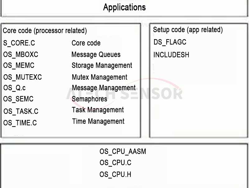
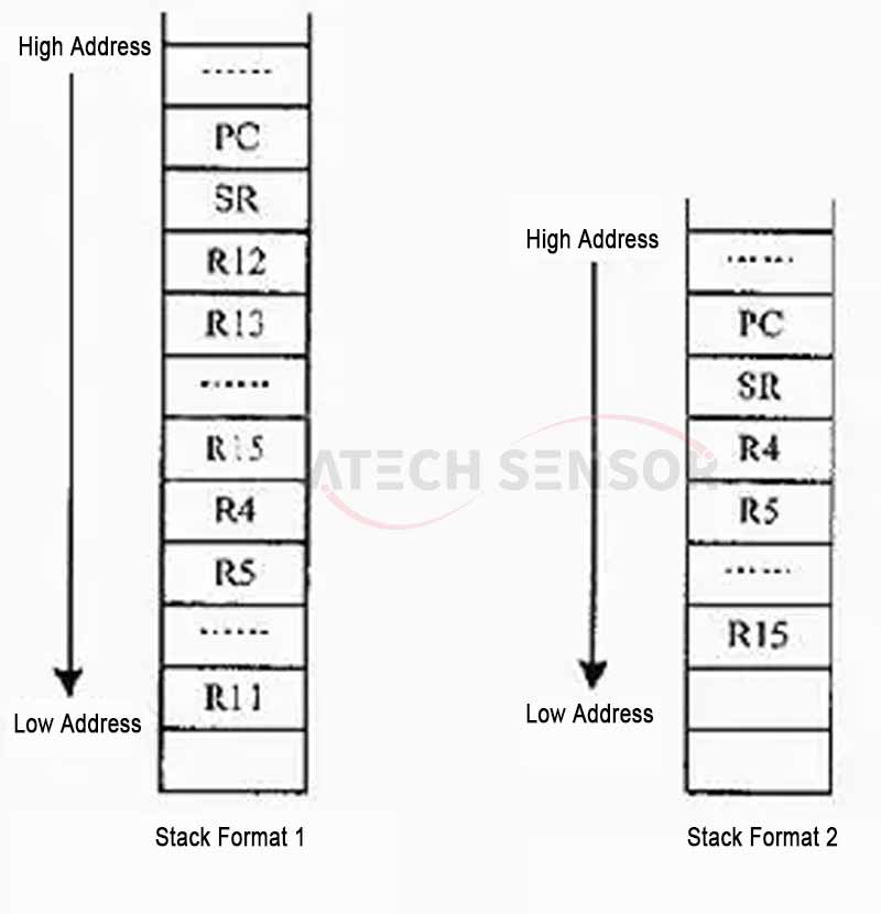
⑴ The transplantation of μC/OSⅡ kernel to S3C4510B should reasonably modify the three processor-related files of μC/OSⅡ according to the characteristics of the processor: OS_CPUH, OS_CPU_AASM, OS_CPU_C.C. It is mainly to change the assembly instructions in the file to the assembly instructions of ARM7, and rewrite the initial values of the registers in the file according to the characteristics of the CPU.
⑵ Memory configuration problem. For the design of memory capacity, the size of μC/OSⅡ kernel code and application code should be considered comprehensively. Each task runs independently, and a separate stack space (RAM) must be provided for each task. The calculation formula for the total RAM is:
Total RAM = RAM requirement of application + RAM requirement of kernel data area + sum of stack requirements of each task + stack required for maximum interrupt nesting
⑶ Implementation of TCP/IP protocol in μC/OSⅡ. In order to meet the requirements of direct information exchange between embedded devices and Internet networks, LwIP protocol stack was ported to μC/OSⅡ.
LwIP is an open source TCP/IP protocol stack for embedded systems developed by Adam Dunkels and others from the Swedish Institute of Computer Science. LwIP means Light Weight IP protocol. LwIP can be ported to an operating system or run independently without an operating system. The focus of LwIP TCP/IP implementation is to reduce the RAM usage while maintaining the main functions of the TCP protocol. Generally, it only needs a few tens of k of RAM and about 40 k of ROM to run, which makes the LwIP protocol stack suitable for use in low-end embedded systems.
The features of LwIP are: support for IP forwarding under multiple network interfaces; support for ICMP protocol; including experimentally extended UDP (User Datagram Protocol); including TCP (Transmission Control Protocol) with congestion control, RTT estimation, fast recovery and fast forwarding; providing a dedicated internal callback interface (rawAPI) to improve application performance.
LwIP can easily add network communication and network management functions to the system under the scheduling of μC/OSⅡ. The LwIP protocol stack was designed with future porting issues in mind. It separates all parts related to hardware, OS, and compiler and puts them in the /src/arch directory. Therefore, the implementation of LwIP on μC/OSⅡ is to modify the files in this directory, and other files should generally not be modified. In the driver, it is mainly based on the Ethernet control special function registers in S3C4510B to write the network interface's packet sending and receiving functions, initialization, and external interrupt service programs for Ethernet controllers.
10. Product procurement
Data collectors are also called inventory machines or handheld mobile computers. Their main features are integration and mobility. They are small in size, light in weight, and have complete functions. They can be operated by hand. Nowadays, using a mobile phone to scan barcodes and enter data into a smart phone can be regarded as a typical example. It is really convenient and practical. In practical applications, how to choose a barcode data collector?
First of all, you need to understand the basic knowledge of data collectors before you can choose a good one. In fact, it integrates scanning and data. Since it can work with batteries, the data collector supports offline operation. It also supports real-time collection and display, storage, transmission and automatic processing of data, making the data accurate, timely, practical and reliable.
When choosing a barcode collector device, you should know that it is generally divided into handheld and fixed types, as well as batch and wireless types. Handheld, as the name implies, can be held in your hand to collect barcode data, while fixed types are fixed in a certain place. Batch data collectors support USB and serial port data cables, communicate with computers, and support offline work. Wireless data collectors connect and update with local application servers at any time through wireless networks. After the barcode is collected, the batch processing method transmits information to the computer through the communication cradle. The wireless method supports real-time data exchange with personal computers. Generally speaking, the price of barcode collectors for batch processing is lower than that of wireless collection. The type to be selected depends on the actual use.
When selecting a data collector, you should also pay attention to the capacity and speed factors. Whenever you use a data collector, you will encounter the problem of how much data to collect. If the amount of data is large, you need to choose a large capacity, which is actually the processing speed. Due to the continuous development of high-end digital circuit technology, in the main structure of the collector, the CPU generally uses a 16- or 32-bit processor, and the higher the number of bits and the main frequency, the stronger the data collection and processing ability and speed of the collector, and the higher the work efficiency. Most of the memory uses FLASH-ROM+RAM type, which can retain information in a long-term non-powered state, and the faster read and write speed ensures the efficiency of operation. The increase in memory capacity makes the one-time data processing faster. Especially when the amount of data is large, the capacity and running speed must be budgeted in advance. Whether it is necessary to support a large screen and a large-capacity battery, some applications require a larger collector screen so that users can easily view the data at any time. At the same time, some occasions require long-term continuous use. At this time, it is necessary to consider the power supply capacity of the battery and how long it can be recharged. Barcode collection equipment, display screens, and CPUs can all bring power consumption, and some structures can support battery operation. Barcode collection scanning and keyboard input are two important device input methods. Most collectors have screens, and they can also support high-precision display of Chinese, English, and graphics as needed.
Consider whether programming is required when purchasing a data collector. More often, after the collector collects the barcode information, it needs to be processed immediately and converted into a directly visible result. This requires secondary programming development based on the device.
Consider the interface when purchasing a data collector. Select the interface of the barcode data collector according to the actual equipment situation. Generally, there are serial ports, infrared ports, and parallel ports that can be connected to multiple types of standard serial and parallel port devices to transmit data, and wireless ones can also transmit data directly.
Data collector equipment should be widely used in various fields such as goods entering and leaving warehouses and express logistics, administrative and enterprise management systems. The above are a few things you should pay attention to when choosing a data collector based on practical experience.
11. Conclusion
The use of the ARM7-based S3C4510B embedded microprocessor can miniaturize the system, facilitate performance improvement and expansion with various peripherals, and reduce costs. As an operating system with open source code, μC/OSⅡ is stable and reliable in specific applications. This system is developed and designed using ARM7+μC/OSⅡ, and has the characteristics of high precision, stable operation, good real-time performance, strong anti-interference ability, and high cost performance. It can be widely used in various industrial occasions, achieving the original intention of the design.